Mapped Mesh—Topology Optimization
Click
Home and then click the arrow next to
Control. Click
 Mapped Mesh
.
Specify the following information in the Mapped Mesh Control dialog box:
• Name—Specify the name of the control or use the default name.
• Meshing Regions—Specify the shape of the meshing region using the Quad or Tri radio button in the Region Shape area. You can use points, vertices, edges, surfaces, volumes, components, mesh region edges or mesh region faces as references for creating a mapped mesh region. You can select existing datum points and vertices or points on edges or faces. Selection of points on edges or faces at a location in the entity creates a datum point at that location. You can select the entities in any order and the system will automatically ensure that the faces are not self-intersecting and have minimum twist.
Tip: As with all collectors, be sure to use the Ctrl key when adding entities to the collector. If you forget to do so, the already collected entities will be replaced with the newly selected entity.
When you edit an existing mesh region by removing one or many of its references, other existing mesh regions are not accessible and a new region cannot be created. Existing mesh regions become accessible only when the mesh region that is being edited is redefined correctly. If two or more edges connect two of the selected points such as circular edges of a cylindrical part, then there can be more than one valid region. In this case, you can pick one of the valid regions from the list.
• Subdivisions—Divide the selected mesh region into triangular or quadrilateral regions.
◦ Default—Set a default subdivision using the Default drop-down list to a value between 1 and 99. The default subdivision value is 10. If you select a value of 5 as default subdivision, then a 5x5 mapped mesh is created.
|  You can use the sim_fem_mapped_mesh configuration option to set the default subdivision values. |
◦ Non-default—Select sets of meshing region edges or edge sets with consistent subdivisions to give them a subdivision value other than the default. You can select nondefault divisions edge set value 2, 5, 10, 20, 50,100 from the Subdivisions drop-down list.
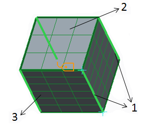
1. Selected edge sets shown by green thick lines
2. Default subdivisions =3
3. Nondefault subdivisions between two edge sets =6
For details about mesh, see the Creo Simulate help.