Requirements for Creating Valid Prismatic Elements
You can use a component or a volume region as a reference for creating a prismatic region. To create prismatic regions with the Prismatic Elements AutoGEM control, the model must meet the following criteria:
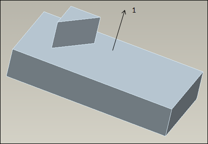
• The volume region or component must have two or more surfaces that are planar or parallel to each other. The planar and parallel surfaces are called the top and bottom surfaces. The direction normal to the top and bottom surfaces is called the extrude direction.
In the following figure the component has three surfaces that can be considered as top and bottom surfaces. The extrude direction is unique because of the geometry of the upper part of the model.
1. Extrude direction of prismatic control
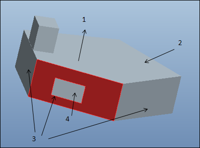
• All other surfaces of the volume or component must be orthogonal to the top and bottom surfaces. These surfaces are called the side surfaces. Side surfaces need not be planar. All edges or curves on the side surfaces must be either parallel or planar to the top and bottom surfaces.
In the following figure a surface region exists on one of the side surfaces. All the edges of the surface region are parallel to the top and bottom surfaces. Hence a prismatic elements control can be created for the selected extrude direction.
1. Extrude direction of prismatic region
2. Top surface
3. Side surfaces
4. Surface region on side surface
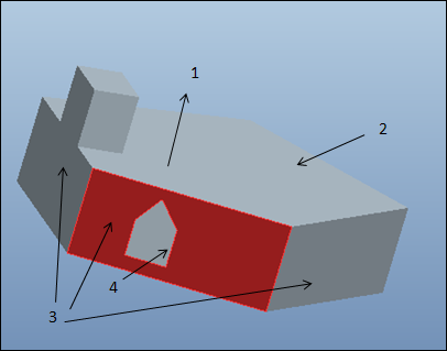
In the following figure the edges or curves of the surface region on the side surface are not parallel to the top and bottom surfaces of the potential prismatic region. You cannot create a prismatic elements control for this model for the selected extrude direction.
1. Extrude direction of prismatic region
2. Top surface
3. Side surfaces
4. Surface region on side surface
• Any volume or component that is referenced and highlighted by a Prismatic Element AutoGEM Control (PEAGC) is called a potential prismatic region. A valid prismatic region is defined to be a volumetric region of the model that contains one or more contiguous and compatible potential prismatic regions. Compatible prismatic regions are those whose extrude directions are identical or opposite to each other. This means that the top and bottom surfaces of all contiguous potential prismatic regions must be parallel.
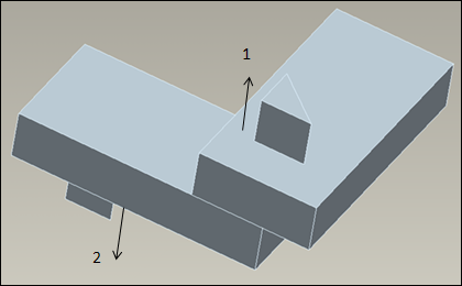
Contiguous parts in an assembly can be designated as prismatic controls as shown in the figure below:
1. Extrude direction of the first component or volume
2. Extrude direction of the second component or volume
In this example the extrude direction for each of the potential prismatic regions is equal and opposite. You can create valid prismatic regions for this model. Note that the top and bottom surfaces of both the components are parallel to each other.
Two or more valid prismatic regions may be separated by a region that is meshed with tetrahedral elements. In this case too, all the components must be contiguous and have compatible prismatic regions. All geometrical (curve) imprints on the boundary of the potential prismatic regions must be parallel or orthogonal to the top and bottom surfaces of the potential prismatic regions.