Sample Process Guide Template
The following sample process guide template StaticAnalysisNative.xml is designed to run a static analysis of a model in native mode.
<ProcessGuideProcess>
<header product="GuidingUI" fileVersion="1.0"></header>
<!-- Process Definition for StaticAnalysis -->
<process id="1" name="StaticAnalysis">
<!-- Assign or create materials -->
<task id="0" Object="Material" Label="Materials">
<description> You must <actionlink>assign</actionlink> materials to the model. Once
the materials assignment dialog appears, select a material from the library and select
the components that will reference it. <br></br>View <infolink href="http://rdweb.ptc.com/dock01/html/usascii/proe/default.htm?promec/start.htm">help</infolink></description>
</task>
<!-- Use default loadset -->
<task id="2" Object="LoadSet" Label="Loadset" name="MyLoadSet">
<description> Define a <actionlink> loadset. </actionlink></description>
</task>
<!-- Create new load in current loadset -->
<task id="3" Object="Load" Label="Loads" Name="LoadOne" type="Force" LoadSet="2">
<description> Define <actionlink> loads </actionlink> that will be applied to the
model. Multiple loads can be created. After you have completed defining the loads,
Select OK from the dialog.</description>
</task>
<!-- Create a new Constraint Set -->
<task id="4" Object="ConstraintSet" Label="ConstraintSet" name="MyConstraintSet">
<description> Define the <actionlink> constraints </actionlink> sets.</description>
</task>
<!-- Create a new contraint in the Constraint Set task -->
<task id="5" Object="Constraint" Label="Constraints" Name="MyConstraint" ConstraintSet="4">
<description> Define the <actionlink> constraints </actionlink> that will be applied
to the model. Multiple constraints can be created. After you have completed defining
the constraints, select OK from the dialog. </description>
</task>
<!-- Creates/Edit MeshControl Task with the name -->
<task id="6" Object="AutoGEMControl" Label="AutoGEMControl" name="MyMeshCtrl">
<description> <actionlink> Execute </actionlink> the AutoGEMControl.</description>
</task>
<!-- Creates/Edit Mesh Task -->
<task id="7" Object="AutoGEM" Label="AutoGEM">
<description> <actionlink> Execute </actionlink> the AutoGEM mesh.</description>
</task>
<!-- Create a new analysis with the LoadSet specified in task 2 and ConstraintSet
in task 4 -->
<task id="8" Object="Analysis" Label="Create Analysis" Name="MyAnalysis" type="Static">
<description> Create a new <actionlink> analysis </actionlink> with default name.</description>
<reference Object="LoadSet">
<id>2</id>
</reference>
<reference Object="ConstraintSet">
<id>4</id>
</reference>
</task>
<!-- Run the analysis created in task 6 -->
<task id="9" Object="Run" Label="Run Anaysis" analysis="6">
<description> <actionlink> Execute </actionlink> the analysis, this may take some
time.</description>
</task>
<!-- Show results for run of the analysis created in task 6 -->
<task id="10" Object="ResultTemplate" Label="View Results" analysis="6" visibility="off"
template="TestTemplate.rwt" mode="combine">
<description> <actionlink> View </actionlink> results for run of the analysis.</description>
</task>
</process>
</ProcessGuideProcess>
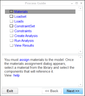
A design engineer can use this template to create a new Process Guide session. When you create a session using this template, Creo Simulate invokes the Process Guide dialog box as shown in the following figure:
All the steps listed in the Process Guide dialog box are based on the associated template. The upper section of the Process Guide dialog box is the Navigation panel while the lower section of the dialog box is the Instruction panel.
If you associate the steps defined in the template with the steps listed in the dialog box, you notice the following points:
• The navigation panel displays the tasks in the same order as defined in the template.
• The name of the task displayed in the Navigation panel is the value specified for the label attribute.
• The text displayed in the Instruction panel is according to the information provided for the description attribute of a task.
• The tasks for which the value of the visibility attribute is set to Off are not displayed in the Navigation panel. For example, see task 10 in the sample for the ResultTemplate object. Process Guide does not display this task in the Navigation Panel.
• The tasks that have a dependency on other tasks refer to those related tasks using the reference object and the TaskID. For example, task 8 in the sample defined for the object Analysis uses the reference objects to link to the corresponding loadset and constraintset tasks through their task ids.
• For the tasks for which the type attribute is defined, the Process Guide invokes the corresponding dialog box. For example, task 3 in the sample for the Load object specifies the value of the type attribute as force. The description attribute for this task provides an action link for a user to invoke the Force/Moment Load dialog box.
If you do not specify the
type attribute while defining the task for the
Load object, Process Guide invokes the
Loads Manager dialog box for managing loads in the model. In addition to the Load object, the Constraint, Material, and MaterialOrientation objects observe the same rule while defining the type attribute.
• To define certain tasks, you need to specify more than the standard set of attributes, that is, id, label, and description. For example, task 8 in the sample for the ResultTemplate object specifies the template, mode, analysis, and visibility attributes.
For details about the Process Guide user interface, refer to
Process Guide dialog box.