To Create a Four-Cavity Mold with Different Core Pins
The task is to create a four-cavity mold that produces four different plastic parts.
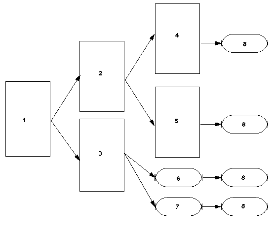
1. PLUG (generic model)
2. HEXAGON
3. SQUARE
4. STAR6
5. STAR8
These plastic parts are instances of one generic part as shown in the illustration. The design part instance names are: HEXAGON, SQUARE, STAR6, and STAR8. Four different core pins are needed to produce different hole shapes.
1. Create a mold. Use Mold Design to create a mold model.
2. Build the RefPart layout. Create the reference part layout. Use the HEXAGON instance as the design part required by the dialog. Enter HEXAGON_REF name for the reference part. Select the Rectangle layout type, specify increment (2 items in the both directions), and the distance between the reference parts.
3. Create reference part instances. Retrieve the HEXAGON_REF reference part in Part mode. Create 3 family table instances (SQUARE_REF, STAR6_REF and STAR8_REF) of the reference part. Add the HEXAGON model as a Merge Part family table item and replace it with SQUARE, STAR6 and STAR8 models for corresponding instances.
Private Name | Merge Part |
HEXAGON_REF | HEXAGON |
SQUARE_REF | SQUARE |
STAR6_REF | SQUARE |
STAR8_REF | STAR8 |
4. Adjust RefPart layout to take instances into account. Redefine the reference part layout with Locate RefPart > Redefine. Switch the layout type to Variable. Replace the HEXAGON_REF reference parts with SQUARE_REF, STAR6_REF, and STAR8_REF instances, as appropriate.
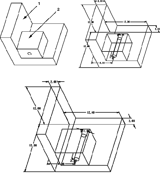
5. Add a workpiece. Assemble or create a workpiece as shown in the illustration:
6. Build a parting surface. Create a shadow parting surface with Parting Surf > Create. Select all reference parts for Shadow creation. Define the Shut-Off plane (XY plane) in this case. Blank the reference parts: Square_ref, Star6_ref, and Star8_ref with the Blank icon on the toolbar.
7. Build volume for core insert. Make sure that MOLD_VOL_SURF_NO_AUTO_ROLLBACK config.pro option is set to YES. Create a core pin volume for the HEXAGON_REF reference part as shown in the illustration and name it HEXAGON_INSERT.
8. Trim the volume to reference part geometry. Click RefPart Cutout to trim the volume by the reference part.
9. Create a Pattern for the volume. Pattern the HEXAGON_INSERT volume to create volumes representing inserts for all the other reference parts. To do this, create a Pattern for all features in the volume.
10. Split the mold. Create the A_CAVITY volume with the Mold Volume > Split menu. Click One Volume and select the shadow parting surface. Select the upper island (a) from the ISLAND LIST as shown in the illustration. The upper island appears in red.
11. Second split. Create the B_CAVITY volume with Mold Volume > Split. Click One Volume. Select the shadow parting surface and all volumes that represent inserts. Select the lower island (b) from the ISLAND LIST as shown in the illustration. The lower island appears in red.
12. Extract all of the volumes with Mold Comp > Extract.
When you complete the extract operation, the four-cavity mold with different core pins appears.
