Example: Creating a Slider
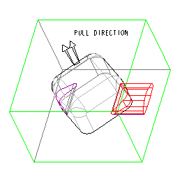
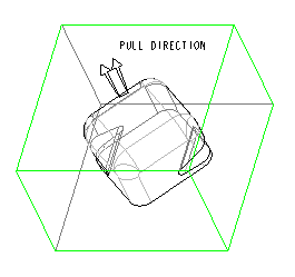
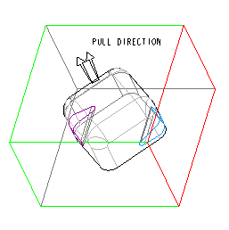
The model where you are going to create a slider is shown in the following illustration. It contains one reference part, with the Pull Direction defined as shown.
1. Click
Mold >
 Mold Volume
 or click
Cast >
 Die Volume
. The
Edit Mold Volume or the
Edit Die Volume tab opens.
2. Click
 Slider
. The
Slider Volume dialog box opens. The reference part and the Pull Direction are selected automatically.
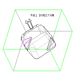
3. Click Calculate Undercut Boundaries. The system identifies the two black volumes, lists Quilt 1 and Quilt 2 in the SLIDER VOLUME dialog box, and displays the boundary quilts in purple, as shown in the following illustration.
4. Select
Quilt 1 in the
Exclude list (the corresponding boundary quilt is highlighted in dark red) and click

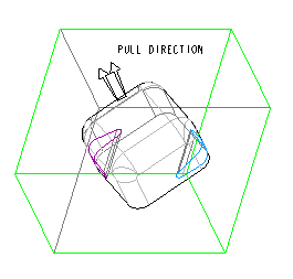
. The system displays the included boundary quilt in blue, as shown in the next illustration.
5. Click

under
Projection Plane and select the side surface of the workpiece (highlighted in red in the following illustration) as the projection plane.
6. Click

. The system displays the slider geometry, as shown in the following illustration. Click

to create the slider.
Repeat the procedure to create a second slider for the black volume on the other side.

 Mold Volume or click Cast >
  Die Volume. The Edit Mold Volume or the Edit Die Volume tab opens.
 Slider. The Slider Volume dialog box opens. The reference part and the Pull Direction are selected automatically.
 . The system displays the included boundary quilt in blue, as shown in the next illustration.
 under Projection Plane and select the side surface of the workpiece (highlighted in red in the following illustration) as the projection plane.
 . The system displays the slider geometry, as shown in the following illustration. Click
  to create the slider.