Automatic Points Generation for Measure Plane
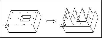
When you choose Automatic from the ADD POINTS menu, the system generates a default 2x2 rectangular grid on selected planar surface, and the Probe Points dialog box appears. The illustration below shows a default grid for Measure Plane.
The grid orientation with respect to the reference coordinate system is defined by the GRID_ANGLE parameter. The UP and DOWN arrows next to each of the input fields in the dialog box let you increase and decrease the number of points in U and V direction. When you click on an arrow, the corresponding value in the input field is changed by 1, and the system redistributes the points according to the new grid. If a point in the grid falls outside the surface boundaries, including internal islands (such as holes or slots), this point is not generated. If you specify a non-zero value for BORDER_CLEARANCE, points within this distance from the surface boundaries are not generated either. The number of points that the system actually placed on the surface appears in the lower-right corner of the Probe Points dialog box. When you click OK, the system generates the default probe path by connecting all the point locations.
The following illustration shows using a 4x3 grid for Measure Plane.


