1. 按一下「架構」(Framework) >  「新連接器元素」(New Connector Element)。「新元件」(New Component) 對話方塊便會開啟。
 「新連接器元素」(New Connector Element)。「新元件」(New Component) 對話方塊便會開啟。
 「新連接器元素」(New Connector Element)。「新元件」(New Component) 對話方塊便會開啟。
 存取資料庫,並從 STEEL CONSTRUCTION INCH > AISC 資料夾中選取非標準連接。元素會出現在預覽區域中。
類型 | 預覽 | 曲面 | 選項 | 數值 |
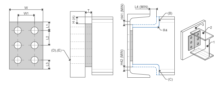
SINGLE SHEAR PLATE |  | Profile side face Profile top Attach face | Offset from top Top beam end cope Bottom beam end cope Profile holes | L1, L2, L3 W, W1 C, H L4_MIN H41_MIN H42_MIN R4 |
SHEAR ENDPLATE |  | I-Profile end Attach face | Offset from top Top beam end cope Bottom beam end cope Attach holes thru next Attach holes thru all | L1, L2, L3 W, W1 H L4_MIN H41_MIN H42_MIN R4 |
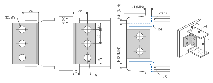
DOUBLE ANGLES |  | Profile side face Profile top Attach face | Offset from top Top beam end cope Bottom beam end cope Profile holes Attach holes thru next Attach holes thru all | L1 L2 L3 W W1 C H L4_MIN H41_MIN H42_MIN R4 |
SINGLE ANGLES |  | Profile side face Profile top Attach face | Offset from top Top beam end cope Bottom beam end cope Profile holes Attach holes thru next Attach holes thru all | L1 L2 L3 W W1 C H L4_MIN H41_MIN H42_MIN R4 |