Example: Creating an Undercut
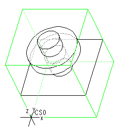
To machine the model shown in the illustration below, you have to create two Flange features, a Boss Top, and an Undercut.
In the following illustrations, each feature is being machined before the next feature is created. This is done just for better clarity of the example. You can define all the features first, and then create the tool paths to machine the features.
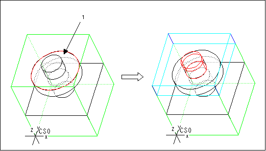
1. Create a Flange feature. Select the top surface of the flange (1) as the Floor surface.
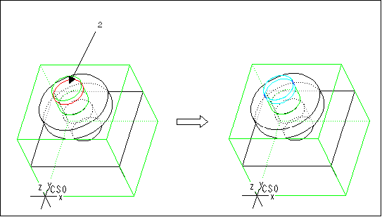
2. Create a Boss Top feature to remove material from the top of the central shaft. Select the top surface of the shaft (2) as the Floor surface.
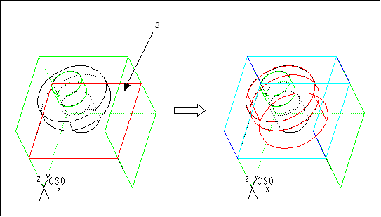
3. Create another Flange feature. Select the top surface of the base (3) as the Floor surface. Note that the system detects the flange and leaves the material around the lower portion of the shaft when it generates the feature geometry.
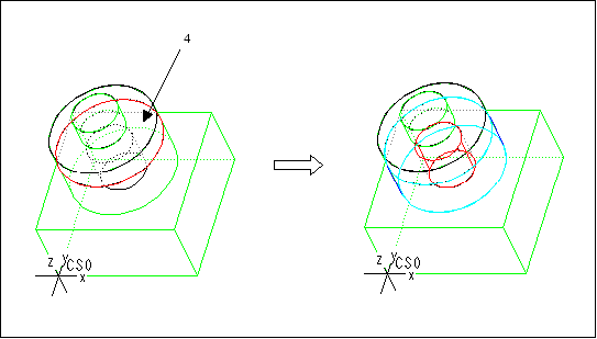
4. Create an Undercut feature. Select the bottom surface of the flange (4) as the Ceiling surface. The system automatically detects the Floor surface and generates the Undercut feature as shown in the following illustration.
