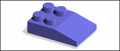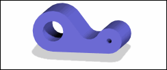

1. |  | |||||
2. | Click > to load
Block2.pk2.
| |||||
3. | Select the lowermost edge of the vertical (side) face and click | |||||
4. | Select the linear dimension, which is closest to the face to be moved, type 200, and press ENTER on the keyboard to stretch the block to twice its original width. | |||||
5. | Select the vertical (side) face of the block, drag the arrow to move the face by 20 units, and press SPACEBAR to open the Option Mini Toolbar (OMT). | |||||
6. | Click | |||||
7. | Select the lowermost edge of the face adjacent to the vertical face, which was moved and click | |||||
8. | Select the midpoint of the linear dimension and move the vertical faces (both sides) connected by the linear dimension. | |||||
| ||||||
1. |  | |
2. | Select the edge of the block and click | |
4. | Drag the arrow on the lateral (top) face to set D1 to 90 units and drag the arrow on the vertical face to set D2 to 25 units. You can also type Distance 1 and Distance 2 values in the Create Chamfer dialog box. |
1. |  | |||
2. | Select a corner of the 3D object and click | |||
3. | Select the lowermost face of the object and shell the object. Click Preview in the Shell dialog box to preview the shelled object. | |||
| ||||
4. | Exclude the four bosses (recognized features) from the shell operation. Click > in the Shell dialog box and drag the cursor to select all four bosses in the viewport. | |||
| ||||
1. |  | |||
2. | Select the cylindrical face of a boss. | |||
3. | Right-click and choose Define Clipping On Axis from the context menu. The viewport shows a clipping plane and the Define Clipping Planes dialog box opens. | |||
4. | Flip the object in the viewport to show the clipping plane in the foreground. | |||
| ||||
5. | Right-click Clipping1 in the structure browser and choose Deactivate in current viewport from the context menu to deactivate the clipping plane. | |||
6. | Right-click Clipping1 in the structure browser and choose Delete from the context menu to delete the clipping plane. | |||
