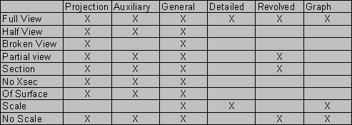
A general view is a view that is independent from other views in the drawing, and shown in the default orientation specified in the Pro/E environment
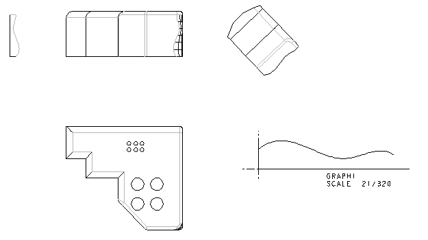
A detailed view is a portion of a model shown in another view. Its orientation is the same as the view from which it is created, but its scale may be different so that you can better visualize the portion of the model that you are creating. The display of edges in a detailed view follows that of the view from which it is created (its parent view).
A projection view is an orthographic projection of another view`s geometry along a horizontal or vertical direction. You can specify the projection type in the drawing setup file by basing it on third angle for ANSI (default) or first angle for DIN.
An auxiliary view is a projection of the geometry of another view at right angles to a selected surface or along an axis. The selected surface in the parent view must be perpendicular to the plane of the screen.
A revolved view is a planar area cross section from an existing view, revolved 90 degrees around the cutting plane projection, and offset along its length. It can be full, partial, exploded or unexploded.
A graph view shows the sketch of a graph feature and its dimensions. The system updates any changes parametrically.
An of flat ply view is a flat single-ply view of a composite model. It can exist in a regular drawing or in sequence drawings.
A copy & align view is an aligned partial view based on a specified view boundary and an alignment relative to the existing partial view.
Note: Detailed, projection, auxiliary, and revolved views have the same representation and explosion offsets, if any, as their parent views. You can simplify, restore, and modify the explosion distance of each view without affecting the parent view. However, detailed views always appear with the same explosion distances and geometry as their parent views.
Moving Views:
If you move a view from which other views were projected (parent view), the projected views (children) also move to maintain view alignment. For example, if you move the top view horizontally, the front view also moves to maintain alignment because it was projected from the top view.
Using the GET POINT menu, you can do exact drafting to place the view where you want it. For example, to exactly align one view with another general view, set the origin using Origin in the MODIFY VIEW menu and the GET POINT menu. This establishes a reference point for moving the view, so that you can easily place it anywhere on a drawing relative to another view.
If the configuration file option "allow_move_view_with_move" is set, DETAIL>Move moves the selected point on the view to the location that you specify by selecting a point. The GET POINT menu is not available.
Using the Draft View command in the TOOLS menu, you can set a drawing view to be the current draft view so the Pro/ENGINEER associates all new draft entities with that view. When you have associated draft entities with a drawing view, they move with the view when you move it, maintaining their location relative to that view. Also, when you scale the view or the drawing, the system scales all draft entities associated with a view by the same factor.
The system uses the view scale of the current view when you create draft entities.
You can create a cross section in Part and Assembly modes and show it in a drawing or you can add it to a view in drawing mode while you are creating it.
A full cross section displays the whole view, whereas a local cross section shows a portion of the model within a closed boundary cross-sectioned, but not outside the closed boundary.
A full & local cross section shows a full cross-sectional view with local cross sections.
A half cross section shows a portion of the model on one side of a cutting plane, but not on the other side.
A total cross section shows not only the cross-sectioned area, but the edges of the model that become visible when a cross section is made.
An area cross section displays only the cross section without the geometry.
An aligned cross section displays an area cross-sectional view that is unfolded around an axis, whereas a total aligned cross section shows an aligned cross section of a general, projection, auxiliary, or full view.
An unfolded cross section shows a flattened area cross section of a general view, whereas a total unfolded cross section shows a total unfolded cross section of a general view.
When a cross-section view cannot be created in Drawing Mode, one of the following error messages may appear:
"Cross-section may be incomplete."
"Cross-section could not be created."
During the creation of a cross-section view in Drawing Mode, Pro/ENGINEER performs an operation on the model analogous to a cut feature. Therefore, if the cross-section cutting plane intersects any "incorrect" geometry, the cross-section view may not be created successfully. In addition, if the cutting plane passes through a tangency point, unattached edge, or vertex either directly or by function of the model accuracy, the cross-section view will not be created.
When a cross-section is made in Part or Assembly mode, it is simply a cosmetic which shows where the section lies in the model. Therefore, no error is given when a section is made through the previously mentioned entities. The following steps are recommended upon encountering an unsuccessful cross-sectional view in Drawing Mode.
Procedure
Be sure that the design intent of the model is clear by first verifying that no geometry checks exist within the model in areas where the cross-section intersects. This action is performed, by retrieving the model and selecting Info from the MAIN menu and Geom Check, if the selection is ungreyed. If available for selection, the information provided in the subsequent menus allows for precise resolutions to geometry issues, which could prevent a cross-section view from being created.
If the selection Geom Check is greyed out, create a cut feature in the model using the exact same placement references and geometry that were used to create the cross-section by selecting Feature, Create, Cut. When the cut feature fails, a "Failure Diagnostics" window will appear, along with an extensive amount of information concerning which feature and/or part the cut could not be made through. The cross-section should be re-designed to avoid the highlighted features, most effectively through offsetting from the intersecting edges or points until the cross- section view can be created successfully in Drawing Mode.
If the problem areas of the model for cross-section creation are still in question, a series of feature and/or part suppressions should be performed in the top-level model. If the drawing model is an assembly, select Component, Suppress from the main ASSEMBLY menu and suppress half of the assembly components. Change Window back to Drawing Mode and attempt to create the cross-sectional view. If the view creates successfully, the troublesome component is not active and will not interfere with the cross-section cut. If unsuccessful at creating the view, try suppressing the other half of the assembly and Component, Resume the previously suppressed components. Once the problem component is determined, continue diagnostic testing at the part level by selecting Feature, Suppress. After determining which feature is causing the cross-sectional failure, modify the cross-section so that it does not pass through any edges, vertices, or tangency points that could possibly cause the cross- section to incorrectly intersect this feature.
Continue to troubleshoot the failed cross-section by indexing, or slightly increasing, the offset position of the cross-section within the model. For planar cross-sections, select X-section, Modify, pick the name of the cross-section, and Dim Values. For offset cross-sections, select X-section, Modify, Redefine and either Section or Scheme. Minor offsets to the dimensions used to originally create and constrain the cross-section should be added. Again, the modified cross-section should continually be tested until the cross-sectional view in the drawing is created successfully.
There are several ways to modify the display of cosmetic thread features while working in drawing mode. They can be erased using the Show/Erase dialog box or they can be blanked on layers. However these modifications will completely remove the display of the threads regardless of the display setting in the environment menu. Cosmetic thread features can also be modified in drawings to conform to ISO or ANSI standard based on the type of view, the location of the feature within the view, and the type of thread. The drawing setup file options "hlr_for_threads" and "thread_standard" are used to modify the display of cosmetic threads. When "hlr_for_threads" is set to "yes", the display of the threads conforms to the standard specified by the option "thread_standard".
Procedure
Figure 1a (ANSI)
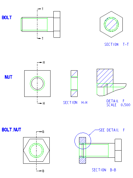
Figure 1b (ANSI)
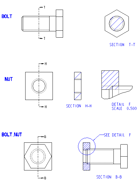
Figure 2a (ANSI)
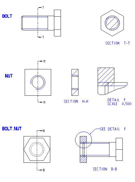
Figure 2b (ISO)

Figure 3a (ANSI)
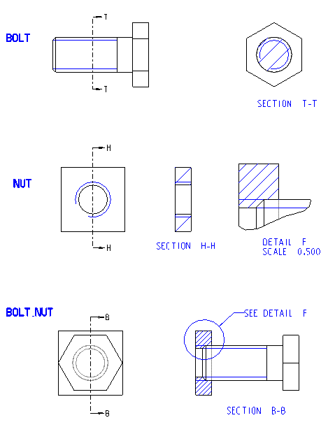
Figure 3b (ISO)
When you create a detailed view of a part containing an axis that lies off the part (That is, model geometry does not enclose it), the axis does not appear in the detailed view.
When you move a broken view, for any subview (or portion of view) that you select to move, all subviews to its right and below it move the same distance. To move the entire broken view to a different location on the drawing, select the upper-left subview (1). This moves the entire view without altering the gaps between the subviews. Selecting any other subview moves all subviews below it and to the right of it the same distance.
An aligned partial view that you create using the Copy & Align command has its own local cross sections. That is, when you create it, it does not have the local cross section of its parent view. You can add them and remove them later.
The Origin and Perspective commands in the VIEW MODFY menu, and the Add Breakout and Del Breakout commands in the VIEW BNDRY are not available for aligned partial views.