
Note: A license of Pro/Feature is required to edit the Pro/PROGRAM for parts (This module is included in nearly all Pro/Engineer packages) and a license of Pro/ASSEMBLY is required to edit the Pro/PROGRAM for assemblies (The Foundation package does include Pro/ASSEMBLY). Check under "Help/Technical Support Info" to make sure you have these modules available. Contact your sales representative if you don't.For design automation, it can be desirable for an assembly to choose the family table instance of a component based on some dimensions or parameters. One example would be choosing a rubber O-ring from a table of supplied sizes based on the piston's diameter and the receiving bore diameter. Fortunately, by doing some simple editing of your assembly's Pro/PROGRAM, this can be accomplished rather simply. For this example, let's add a little more complexity.
To use a c-clamp in an automatic fashion, it would be nice if the size of the clamp was chosen automatically AND the jaw was opened to the correct size to accommodate the stock we're clamping. Pro/PROGRAM can accommodate both needs.
Note: If you've never used Pro/PROGRAM before, click here for a quick primer.
The process of solving this issue can be broken into 4 steps
1) Setting the assembly parameters.
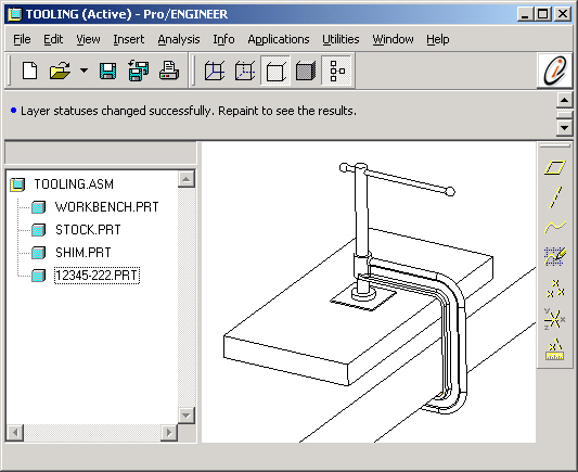
2) Assembling the required components into the assembly.
3) Modify the Assembly Pro/PROGRAM to choose the correct
family table instance of the c-clamp
4) Modify both the Assembly and Part Pro/PROGRAMS
to enable the jaw to open to the correct size.
A follow-up summary flowchart makes it all clear.
These parameters could set manually, they could be measurements or they might just as well be dimensions. Whatever the source of the values, they must be known to the assembly.
VERSION
REVNUM 126
LISTING FOR ASSEMBLY TOOLINGINPUT
END INPUTRELATIONS
END RELATIONS
ADD FEATURE 1
INTERNAL FEATURE ID 1
TYPE = DATUM PLANE
NAME = ASM_RIGHT
FEATURE IS IN LAYER(S) :
01__ASM_ALL_DTM_PLN - OPERATION = SHOWN
01__ASM_DEF_DTM_PLN - OPERATION = SHOWNEND ADD
....
(other assembly features here)
....ADD PART WORKBENCH
INTERNAL COMPONENT ID 39
END ADDADD PART STOCK
INTERNAL COMPONENT ID 40
PARENTS = 39(#5)
END ADDADD PART SHIM
INTERNAL COMPONENT ID 50
END ADDADD PART C-CLAMP
INTERNAL COMPONENT ID 41
PARENTS = 39(#5)
END ADDMASSPROP
END MASSPROP
The format for lookup_inst is:For our c-clamp part, the family table parameters we want to consider are "JAW_HEIGHT" and "THROAT_DEPTH".
lookup_inst ("generic_name", match_mode, "param_name_1", match_value_1, "param_name_2", match_value_2,...)
- where
· generic nameName of the generic model with a .prt or .asm extension
· match_modeOne of the following values:
- 1 (find closest instance with param values less than or equal to supplied values)
- 0 (find instance with param values that match supplied values exactly)
- 1 (find closest instance with param values greater than or equal to supplied values)
· param_name_1Family table parameter name
· match_value_1Value to match against
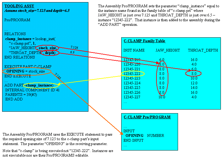
clamp_instance = lookup_inst("c-clamp.prt", 1, "JAW_HEIGHT", stock_size, "THROAT_DEPTH", depth)
Remember, stock_size and depth are the two assembly parameters we defined earlier. Match_mode=1 will insure we choose the next larger c-clamp and not the next smaller. So our assembly relations block in the Pro/PROGRAM now looks like this:
RELATIONSWe also need to make sure that the assembly grabs the correct instance. At this point, only the parameter, "clamp_instance", has been set. Nothing's been chosen yet.
clamp_instance = lookup_inst("c-clamp.prt", 1, "JAW_HEIGHT", stock_size, "THROAT_DEPTH", depth)
END RELATIONS
Down in the Pro/PROGRAM listing, we find the "ADD PART" statement. We need to modify this to assembly the instance instead of the generic. To do this, "ADD PART C-CLAMP" will become "ADD PART (clamp_instance)". The parameter placed in parenthesis tells Pro/Engineer to substitute the value of the parameter for the part name.
So the Pro/PROGRAM now looks like this
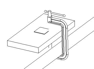
...And the assembly looks like the following. Notice that the correct c-clamp was chosen but the jaw opening is still wrong causing hidden line problems.
ADD PART (CLAMP_INSTANCE)
INTERNAL COMPONENT ID 41
PARENTS = 39(#5)
END ADD
...
Part 1) is accomplished by adding a parameter to the INPUT block of the Pro/PROGRAM for the C-Clamp part. INPUT statements take the form of "variable type". The type can be "number", "string" or "yes_no". We've set the symbol of the dimension which controls the opening to be "OPENING". Therefore, the input block looks like the following:
INPUTPart 2) is accomplished by adding an EXECUTE statement to the assembly Pro/PROGRAM. The EXECUTE statement passes the parameters and values listed to the part or assembly being executed.
OPENING NUMBER
END INPUT
The format of the EXECUTE statement is:
EXECUTE PART part_name
parameter1 = value1
parameter2 = value2
...
END EXECUTE
Substituting the information for this assembly,
EXECUTE PART C-CLAMPNotice that we're not executing the instance but rather the generic. Instances cannot be executed you must use the generic. In the same way, instances cannot have their Pro/PROGRAM modified either.
OPENING = STOCK_SIZE
END EXECUTE
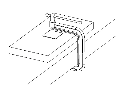
Once that's all done, a single regeneration of the assembly produces the following. It looks great, the BOM is correct, and hidden lines are no longer a problem!
The final Pro/PROGRAM follows. Parts that were changed or added are in bold. Some assembly features were removed for brevity.
VERSION
REVNUM 165
LISTING FOR ASSEMBLY TOOLINGINPUT
END INPUTRELATIONS
CLAMP_INSTANCE = LOOKUP_INST("c-clamp.prt", 1, "JAW_HEIGHT", STOCK_SIZE, "THROAT_DEPTH", DEPTH)
END RELATIONSEXECUTE PART C-CLAMP
OPENING = STOCK_SIZE
END EXECUTE
ADD FEATURE (initial number 1)
INTERNAL FEATURE ID 1
TYPE = DATUM PLANE
NAME = ASM_RIGHT
FEATURE IS IN LAYER(S) :
01__ASM_ALL_DTM_PLN - OPERATION = SHOWN
01__ASM_DEF_DTM_PLN - OPERATION = SHOWNEND ADD
....
(other assembly features here)
....
ADD PART WORKBENCH
INTERNAL COMPONENT ID 39
END ADDADD PART STOCK
INTERNAL COMPONENT ID 40
PARENTS = 39(#5)
END ADDADD PART SHIM
INTERNAL COMPONENT ID 50
END ADDADD PART (CLAMP_INSTANCE)
INTERNAL COMPONENT ID 41
PARENTS = 39(#5)
END ADDMASSPROP
END MASSPROP
A typical design listing may contain any of the following:
· Input variables with their current values
· Relations
· IF-ELSE clauses
· Lists of all the features, parts, or assemblies
in the design which, when enclosed within "IF condition... ELSE... END
IF" statements, create alternate
design branches
· EXECUTE statements (Assembly mode only)
· INTERACT statements
· Feature suppression and order
· MASSPROP statement
A part's or assembly's Pro/PROGRAM can be accessed via the "Program" menu pick at the top level of either the part or assembly menus.
Before diving into Pro/PROGRAM, it is highly suggested that you review the information in the online help system. Look in the index under Pro/PROGRAM. There are about 40 pages of information in the help system. Both capability descriptions and good examples are included.
There's also good information in our Technical Support Knowledge
Database. Some links are listed below (You'll need a customer support
login to access these).
Frequently Asked
Questions - Relations, Pro/Program, and Layers
Suggested
Technique for Using Pro/PROGRAM to Create Instances
TITLE :
Using UDF's to Facilitate the Assembly Process
Just have too many similar colors? By labeling them, much of the confusion of which one to use goes away. Notice the "Cold_Steel" label in the following image.
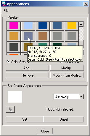
This is accomplished by using one of the detail fields (Texture, Bump, Decal) in the color.map file to label the color.
The Decal field is probably the least used so it's perfect for this.
You'll need to edit the color.map file with a text editor. Locate the 3rd line of each color and replace the last "NO_TEXTURE" field with the color name. Make sure not to include any spaces in the name.
File: color.map
...
1.000 0.770 0.060 0.900 0.900 0.800 1.000 1.000 1.000 1.000
0.000 0.250 0.000 0.500 0 90
NO_TEXTURE NO_TEXTURE Corn_Yellow_Shiny
0.820 0.600 0.240 0.900 0.900 0.800 0.500 1.000 1.000 1.000
0.000 0.250 0.000 0.500 0 90
NO_TEXTURE NO_TEXTURE Tan_Glossy
0.440 0.500 0.600 0.900 0.900 0.800 1.000 1.000 1.000 1.000
0.000 0.250 0.000 0.500 0 90
NO_TEXTURE NO_TEXTURE Cold_Steel
0.640 0.460 0.300 0.900 0.900 0.800 0.370 1.000 1.000 1.000
0.000 0.250 0.000 0.500 0 90
NO_TEXTURE NO_TEXTURE Brown_Chalky
0.550 0.550 0.550 0.900 0.900 0.800 1.000 1.000 1.000 1.000
0.000 0.250 0.000 0.500 0 90
NO_TEXTURE NO_TEXTURE Aluminum_Polished
0.550 0.550 0.550 0.900 0.900 0.800 1.000 1.000 1.000 1.000
0.000 0.250 0.000 0.500 0 90
...