PTC
Email Newsletter
April 30, 2001
This
Weeks Topics:
A) PTC Product
Focus:Pro/ENGINEER Mechanism Design Extension
B) Tip of the
week:Analysis and Utility Features
Found in Sketcher Mode
C) Upcoming
Events and Training Class Schedules
A)
PTC Product Focus: Pro/ENGINEER Mechanism Design
Extension
The
Pro/ENGINEER Mechanism Design Extension (P-MDX) provides
engineers within the product develoment process to persrom
kinematic motion simulation and behavioral insight into the
assembly through the easy defintion and animation of connections
with Pro/ENGINEER, such as pin joints, ball joints and sliders.
These connections, and resulting assembly constraints, facilitate
the easy assembly of closed loop systems, like four bar linkages.
These connections can be used compatibly and in combination with
packaging and traditional Pro/ENGINEER constraints like mate,
align and insert. Once assembled, engineers can observe how their
mechanism designs will behave geometrically through interactive
part dragging and user-defined motion simulations. Any point on a
mechanism assembly can be dragged interactively by the user to
animate the mechanism. Predefined motion simulations, using
drivers to simulate motors or actuators, also provide animation.
While a full dynamics simulation yielding velocities,
accelerations, and forces must be achieved using Pro/MECHANICA
Motion, Mechanism Design is a powerful design tool enabling
engineers to create industry-best mechanism designs by clearly
building and communicating ‘design intent’ into
mechanism assemblies and subassemblies. MDX is an option to
Pro/ENGINEER-Foundation.
Key
Product Features
Mechanism
Design functionality allows design engineers to:
- Easily
define mechanism design within Pro/ENGINEER: Mechanism
Design is completely integrated within the Pro/ENGINEER
environment: The user works with the same user interface,
operates on the same geometry model, and uses the same
visualization, file manipulation, graphics, and printing
tools.
- Animate
mechanism assemblies through interactive dragging and
user-defined motions:
The user
can pick on any position on any part within a mechanism
assembly and, by use of the mouse, interactively drag the
part to create movement within the whole mechanism. By
using drivers to represent motors or actuators,
user-defined motion sequences can be created, stored, and
played back at any time.
- Detect
interference and clashes:
Interference
and clashes can be detected during user-defined motion
playback and the interference volume calculated at any
time during the motion.
- Integrate
results with Pro/MECHANICA Motion and Design Animation:
The joint
and driver information defined in Mechanism Design is
inherited by Pro/MECHANICA Motion and Design Animation so
that early design intent can be reused for dynamic
mechanism simulation and during definition of animation
sequences.
Many of PTC's
products incorporate motion. The following is a table designed to
highlight the differences between these packages.
Motion
Product Comparisons (version 2001)
| Function |
Behavioral
Modeling (includes MDX) |
Mechanism Design
(MDX) |
Design Animation
(DAO) |
Pro/MECHANICA
Motion |
| Setup |
| Work inside Pro/E
environment |
X |
X |
X |
X |
| Define joint types |
X |
X |
|
X |
| Define joint types based
on assembly constraints |
X |
X |
|
|
| Joints inherited by DAO |
X |
X |
N/A |
|
| Joints inherited by
Mechanica Motion |
X |
X |
N/A |
N/A |
| Study mechanisms with
cams & slots |
X |
X |
X |
X |
| study mechanisms with 3D
slots |
X |
X |
X |
|
| Study mechanisms with
gears |
|
|
|
X |
| study mechanisms with
general contact |
|
|
|
X |
| Create drivers |
X |
X |
X |
X |
| Create time-conditional
drivers |
X |
X |
X |
|
| Drivers inherited from
MDX |
N/A |
N/A |
X |
|
| Apply loads |
|
|
|
X |
| Write programs for
custom load applications |
|
|
|
X |
| Create measurements
(angle, distance, etc) |
X |
|
|
X |
| Create measurements
based on loads |
N/A |
N/A |
N/A |
X |
| Dynamically drag
mechanisms |
X |
X |
X |
|
| Generate key frame
(snapshot) sequence |
|
|
X |
|
| Organize animation into
a timeline |
|
|
X |
|
| Lock bodies over a
specified time period |
|
|
X |
|
| Save Pro/E views with
animation |
|
|
X |
|
| Save Pro/E display
states with animation |
|
|
X |
|
| Create assembly/
disassembly & maintenance sequences |
|
|
X |
|
| Perform sensitivity
& optimization studies |
X |
|
|
X |
| Results |
| Check interference over
range of motion |
X |
X |
X |
X |
| Plot clearance or volume
of interference over range of motion |
X |
|
|
|
| Plot measurements
(angle, distance, etc.) over range of motion or
versus another measure. |
X |
|
|
X |
| Calculate reaction loads |
|
|
|
X |
| Transfer loads to
Mechanica Structure |
|
|
|
X |
| Play animation |
X |
X |
X |
X |
| Animate reaction force
arrows during animation |
|
|
|
X |
| View and save trace
curves |
X |
X |
|
X |
| View and save
envelope/cam synthesis curves |
X |
X |
|
X |
| View and save 3D trace
curves |
X |
X |
|
|
| Export MPEG1 |
X |
X |
X |
X |
| Generate Motion Envelope2 |
X |
X |
X |
X |
| Save multiple sets of
results |
X |
X |
X |
|
| Other
considerations |
| C-compiler requirement |
|
|
|
X |
| Intralink support |
X3 |
X3 |
X3 |
X4 |
| Floating license |
X5 |
X5 |
X6 |
X6 |
| Training |
Note7 |
Note7 |
Note7 |
X (3days) |
|
- MPEG is available in build 1999310 and
higher of Pro/E.
- All products enable you to generate a
frame file (*.fra). This and a license of Pro/E are the
only requirements for generating motion envelope.
- DAO and MDX store information in the
assembly files. Table files (*.tab) are supported.
Results (*.pbk, *.pba) and frame files (*.fra) are not
supported automatically.
- The assembly file, *.mda, and table files
(*.tab) are supported. Results (*.res), motion loads
(*.mml) and frame files (*.fra) are not supported
automatically.
- Extensions float with a particular
license of Pro/E.
- Options float independently of Pro/E.
- Online help and online tutorials should
be sufficient to learn the software. A training course
for MDX is being developed.
The
following is a brief overview of the steps involved in creating a
mechanism. The example used is a wine bottle decorker shown here:
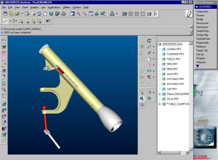
I
will assemble the handle of the de-corker to show how mechanism
connections are made. Here we see the normal assembly contraint
dialog box with one difference...the connections menu shown here.
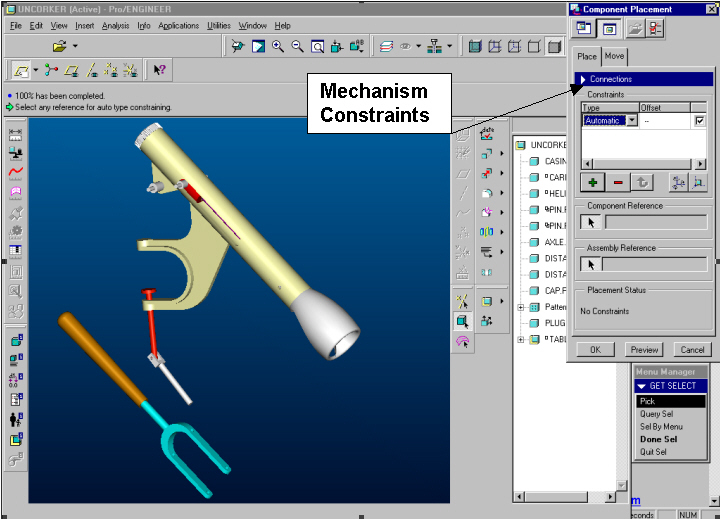
With
MDX installed, clicking on this menu brings up a hole new list of
mechanism constraints.

Most
are familiar with the mate, align, offset, etc. constraints from
assembly mode, mechanisms contraints are listed above (rigid,
pin, slider, etc.). These tell MDX how the movement at these
connections is to occur. I will assemble the fork and link
components using pin joints shown here.

Once
all the component mechanism connections are defined, the motion
can be run. Motion can be output as a graph showing velocity,
position, and acceleration of any combination of points on the
assembly. The assembly can be checked for interference
issues and motion envelopes can be generated to aid in the design
of components by others. The following is the resulting motion
exported as an AVI file.
Motion Video
This was a very
brief overview of a powerful analysis tool, for further
information on MDX please visit the product webpage at: http://www.ptc.com/products/proe/mdx/index.htm
BACK
TO TOP OF PAGE
B)
Tip of the week: Analysis and Utiltiy Features Found in
Sketcher Mode
With
the Release 2000i2 of Pro/ENGINEER new analysis features have
been
added in sketcher mode.
To Obtain
Information About Section Geometry
1. Click
Analysis-Section Analysis.
2. Select a
command from the Section Analysis menu:
- Entity-Select
a single entity about which to get information. The
system displays the type of geometry, endpoint
tangencies, and endpoint coordinates (only if a
coordinate system is selected).
- Intersect
Pt-Select two entities to determine their intersection
points. If the selected entities do not physically
intersect, Sketcher extrapolates the entities to find an
intersection. If the extrapolated entities do not
intersect (for example, parallel lines), the system does
not return an intersection value. The system displays the
angle of slope at the intersection point for both
entities and the intersection coordinate values (if a
coordinate system is selected).
- Tangent
Pt-Select two entities to determine where their slopes
are equal. The selected entities do not have to be
touching. The system displays the angle of slope at the
tangency points, the distance between the two tangency
points, and, if a coordinate system is selected, the
coordinates of the tangency points.
- Distance-Measure
the distance between any two parallel lines, two points,
or a point and a line.
- Angle-Measure
the angle between any two lines. Select the two lines.
Pro/ENGINEER displays the measured angle in the Message
window.
- Curvature-Display
the curvature of splines in the section using the CRV
DISPLAY menu options. The options in the CRV DISPLAY menu
are as follows:
1.
Select Curve-Select a curve for curvature analysis
display.
2.
Scale-Change the scale of the curvature display.
3.
Density-Change the density of the curvature display.
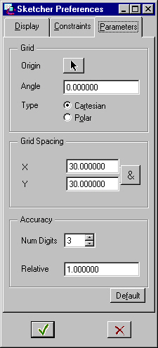
With
the Release 2000i2 of Pro/ENGINEER new sketcher preferences have
been
added in sketcher mode.
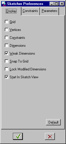
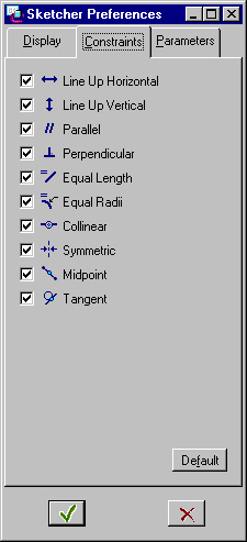
Another new
feature is the location of the Sketcher Preferences under the
Utilities menu while in sketcher mode. As seen in the following
screen shots, there are a multitude preferences to modify to best
suit your sketching style.
BACK TO
TOP OF PAGE
C) Upcoming Dates: Events and
Training Class Schedules
Updated: April 02, 2001
PTC Innovation Days!!! (Product Development Workshops)
Your Personal Invitation: http://www.thetroupe.com//Pub/PTCWEB/ptcnew.html
Accelerate your product
design and development!
Denver, CO - May 16 or 17th
Hotel Boulderado
2115 13th Street
Boulder, CO 80302
Phone: 303-442-4344
Attendees receive a FREE
seat of Pro/ENGINEER 2001, the student edition!!! (Scheduled release May, 2001)
_________________________________________________________________________________
Denver (Englewood, Co.) Training Schedule:
10% TRAINING DISCOUNT
Effective
immediately, from now until May 31, 2001 we have been authorized
to offer a
10% discount on all MCAD
training classes held in the Englewood, CO training center.
Terms and
Conditions:
-Offer
good on all MCAD classes from now until May 31, 2001.
-Offer good for classes
held in the PTC Englewood, CO training center ONLY
-Offer is also valid for
customers with previously negotiated contract discounts!
**Courses can be
initiated with a minimum of 5 people if the class is not listed
above.
Click here to register for any class!
BACK TO
TOP OF PAGE
| Note:
This weekly PTC email will continue to be used for the
following: 1)
Inform you of events related to PTC products. (user
groups, conferences, training schedules, etc.)
2) Educate you on products
that are available at PTC
3) Tips and Techniques
using PTC products
|


