PTC
Email Newsletter
March 6, 2001
A)
PTC Product Focus: Advanced
Assembly
EXtension
B) Tip
of the week: Surface Transforms
A)
PTC Product Focus: Advanced
Assembly
EXtension
AAX
expands the power of Pro/E Foundation to encompass the engineering and
management of medium to very large assemblies. It offers high powered tools
for design criteria management, top-down assembly design, large assembly
management, Shrinkwrap, and process planning. These tools enhance the productivity
of design teams creating and managing very large, complex product designs
– and help downstream users produce accurate lifecycle documentation and
assemble these complex products on the shop floor.
When do you use AAX?
*When your assembly or part designs become too
large to regenerate in a timely manner.
*If you want to employ Top Down Design procedures.
*If you want to use skeleton models.
*If you need to create assembly documentation
that includes multiple explode states and multiple BOM representations.
*If you want to communicate proprietary designs
with outside suppliers, in a secure manner.
Key Product Features and capabilities:
Advanced
Assembly Design
*Top Down Design: use skeleton models to define and drive top level
assembly design criteria.
*Interchange Assemblies: Allows users to relate independent but functionally
equivalent parts, so these can be easily switched in the context of a particular
design.
*Simplified Representations: Collect specified components for better
graphical display performance based on rules such as: model size, location,
name, or any other parameter.
*Associative Shrinkwrap: Creates a lightweight surface representation
that includes mass properties. This greatly improves system performance
and allows you to send suppliers accurate and associative models without
revealing the proprietary design information.
Process
Planning
*A complete assembly process documentation tool. Create complete
(and accurate) assembly documentation for the shop floor.
*Depict only the components present in a given assembly step.
*Automatic BOM's that only reflect the components assembled up to a
particular step.
*Create multiple exploded views with jogged offset assembly lines.
Design Criteria
Management
*2d Graphical Layouts: Create conceptual stage drawings that include
information such as: global parameters, relationships, constraints, and
requirements.
*Automatic assembly: Users can create a placement correspondence among
multiple components in the assembly by declaring the same axis or plane
in different components in the assembly to the layout. The software then
can locate components with common declarations based on this knowledge
- to automatically combine them in an assembly.
B)
Tip of the week: Surface Transforms
Have you ever wanted to pattern complex geometry but couldn't because
of the references you picked?
Do you have a model that has a long regeneration time because of a
large pattern?
If you answered yes to either one of those questions, Surface Transforms
could be the answer for you!
Definitions (in Pro/E terms):
*What is a surface quilt?
A surface quilt is a "patchwork" of connected surfaces. A quilt may
contain one or more surface patches. The external edges of a surface
are yellow, and the internal boundaries of the patches are displayed in
magenta.
*What is a transform?
A transform feature enables surface quilts and/or datum curves to be
translated, rotated, or mirrored. This functionality is accessed
through Feature, Create, Surface, Transform.
*What is a "tweak patch"?
A tweak patch allows one or more solid surfaces to be replaced with
a surface feature. Tweak patch features can both add and remove solid
material at the same time. This functionality is accessed through Feature,
Create, Tweak, Patch.
Benefits of using Surface Transform:
1) Fast regen times:
*It only copies the final geometry making it extremely efficient for
regen times.
*Does not have to re-specify references to parents.
2) Complex geometry manipulations:
*Dimensioning methodology does not constrain the type of pattern or
copy you use.
*Similar to an Identical pattern as all of the geometry is the same.
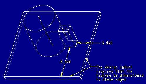
An example: Radial pattern of a feature with no
embedded angular dimensions.
| 1) This is an example of geometry that could not be patterned because
there is no angular dimension. |
 |
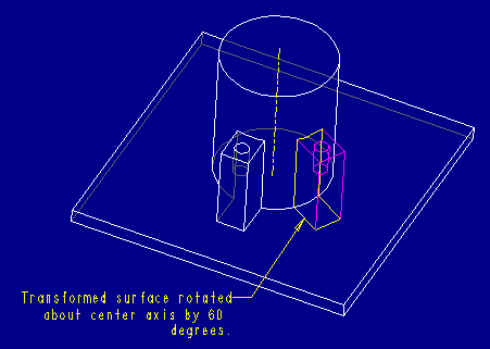
| 2) Create a surface copy of existing geometry (include the small hole
in the center). |
| 3) Transform the surface about a radius a specified angle (results
shown here) |
 |
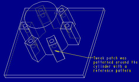
| 4) Fill the transformed surface with solid material using "tweak patch" |
| 5) Pattern the transformed surface. |
| 6) Ref pattern the "tweak patch" feature. The resulting geometry
looks like this! |
 |
Summary: (Go
here for the complete description of technique)
*We are able to pattern geometry that would have been impossible with
standard pattern tools.
*The end model will regenerate faster because the resulting geometry
is patterned (not all the individual features that make it up).
*The surface features we patterned are essentially "consumed" by performing
the tweak patch.
*This works for both protrusions (where material is added) and cuts
(where material is removed).
*This technique can be used in virtually any circumstance where complex
geometry needs to be patterned or copied!
Updated: March 6, 2001
|
Date
|
Class Name
|
| 3/12 |
Fundamentals of Design |
| 3/26 |
Introduction to Pro/Engineer |
| 4/2 |
Pro/Intralink Administrator Training |
| 4/9 |
Fundamentals of Pro/Mechanica (Structure/Thermal) Training |
| 4/16 |
Pro/Diagram |
| 4/18 |
Cable Harness Design and Manufacturing Training |
| 4/23 |
Introduction to Pro/Engineer |
| Note:
This weekly PTC email will continue to be used for the following:
1) Inform you of events related
to PTC products. (user groups, conferences, training schedules, etc.)
2) Educate you on products
that are available at PTC
3) Tips and Techniques using
PTC products
|


