
February 5, 2001
Pro/ECAD is a linking translator included on every Foundation license
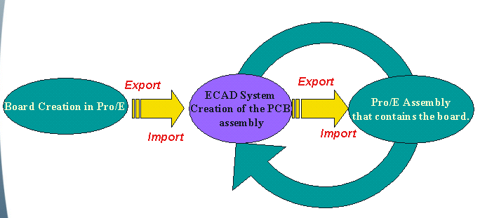
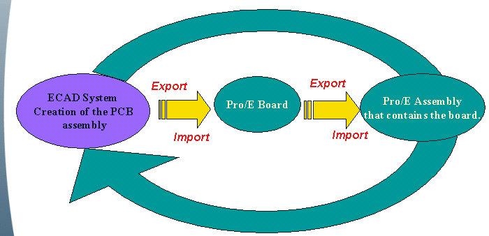
It allows the PCB (Printed Circuit Board) engineers to translate their design into Pro/E. It also allows the mechanical engineers to translate critical information into the PCB design tool.

The interface can support design processes in which the design originates in Pro/ENGINEER or in the Board Design tool: both depicted below.
What can be transferred?
Which ECAD tools are supported?
Can the two disciplines (MCAD and ECAD) work concurrently?
How does a Pro/ENGINEER user benefit?
B.)Tip of the Week: Model Notes
Model Note functionality can be useful in many Scenarios - At least one of which has nothing to do with displaying text in 3D. Here are some examples:
Model notes are text strings that you can attach to design objects in Pro/ENGINEER. You can attach any number of notes to any object in your model. When you attach a note to an object, the object is considered the “parent” of the note. Deleting the parent deletes all of the notes of the parent. You can attach model notes anywhere in the model, they do not have to be attached to a parent. The attachment is the end point of the model note leader line. You can use model notes to:
To create and attach a model note:
1. From the PART or ASSEMBLY menu, Click Set Up > Notes > New. OR With the cursor on an assembly, feature, part, or component in the Model Tree window, press the right mouse button and choose Note Create from the resulting popup menu. The Note dialog box opens.
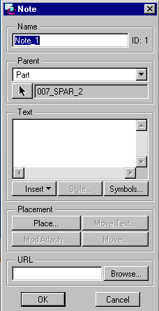
2. (Optional) Under Name, replace the default name with a name that you prefer.
3. Under Parent, Click the type of model entity that will be the parent of the note, and select the entity if necessary. For assemblies, the choices are Part, Feature, Assembly, Subassembly, or Component. For parts, the choices are Part or Feature.
4. Under Text, type the text for the note or click Insert to place existing text from a file or another note into this note.
5. If you need a special symbol in your note, click Symbols to display the Symbol Palette, and then click the symbol or symbols that you want. Symbols appear at the cursor location in the text area of the Note dialog box. Click Close to return to the Note dialog box.
6. (Optional) Under Placement, click Place. The NOTE TYPES compound menu appears. Note: If you do not place the note, it will not appear in the 3-D graphics window.
7. Click Leader, No Leader, or On Item (or Offset or ISO Leader when appropriate, not dimmed) to indicate the type of note you want, and from the following other options: ̃ Standard-Uses the default leader type. ̃ Normal Ldr-Makes the leader normal to the entity; in this case, the note can have only one leader. ̃ Tangent Ldr--Makes the leader tangent to the entity; in this case, the note can have only one leader. Then click DONE.
8. If you Click Standard as the leader type, specify the attachment by choosing one of the following from the ATTACH TYPE menu: ̃ On Entity-Creates a note with a leader that is attached to a model edge or draft geometry. Selecting the entity near its vertex locates the leader at the vertex. ̃ On Surface-Locates the leader on model geometry or surfaces. You can select model geometry, threads, and datum surfaces. After you make an attachment on a surface, if you reorient the view, the attachment remains. If the size of the surface changes, the system updates the leader point accordingly. To modify or delete existing surface attachments, use the Mod Attach command in the DETAIL menu. For Standard, Normal Ldr, and Tangent Ldr types of notes, you can choose from the following additional options. If you choose Normal Ldr or Tangent Ldr, these options appear on the LEADER TYPE menu: ̃ Arrow Head-Creates a leader with an arrow head. ̃ Dot-Creates a leader with a dot. ̃ Filled Dot-Creates a leader with a filled dot. ̃ No Arrow-Creates a leader with no arrow. ̃ Slash- Creates a leader with a slash. ̃ Integral-Creates a leader with an integral. ̃ Box-Creates a leader with a box. ̃ Filled Box-Creates a leader with a filled box. ̃ Double Arrow-Creates a leader with a filled box. (Some seem to work for edges and some for surfaces.) Any combination of the ATTACH TYPE menu commands is possible. Choose a command and locate the leader; choose another command and locate that leader, until you have finished.
9. When you have finished choosing the commands for leader lines, and have selected an endpoint (either free or on an entity), Click ATTACH TYPE > Done.
10. The note appears in the specified location attached to the edge geometry with leader lines.
11.(Optional) Under URL, type a World Wide Web address that you want to associate with your note. This is useful, for example, for attaching specifications to parts of a model.
12. Select a location on the model for your note and click OK. The system creates the note.
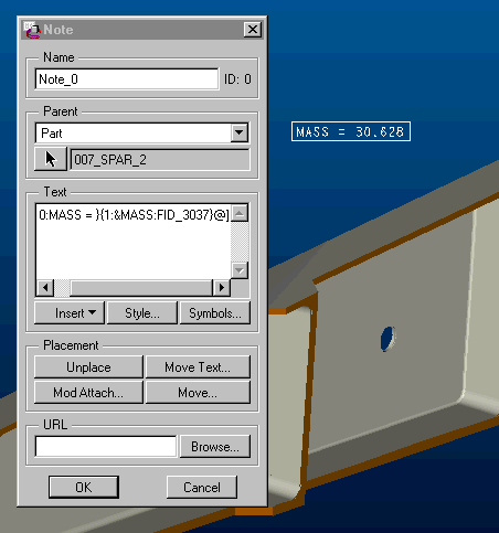
Example 1. The note pictured displays the results of a model analysis and updates as the model changes
Example 2. Ever wanted a string parameter to include carraige returns?
I do not believe that string parameters can include carriage returns. But, Model Notes can and string parameters can be set equal to model notes.
So, say we have three parameters that fill in a three line title on a drawing: LINE1, LINE2, and LINE3. We want the title to always be centered whether there is one line, two lines, or three lines. Create two Models notes as shown below:
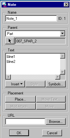
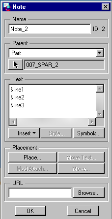
Use >Set Up;>Parameter;>Create;>Note to create two notes. I called them twoline (set equal to model note1) and threeline (set equal to model note2 in my case; may be different in your model) Add the following relations to set the value of TITLE and use TITLE to automatically fill in the title block on your drawing.
TITLE = LINE1
IF LINE2 != ""
TITLE = TWOLINE
ENDIF
IF LINE3 != ""
TITLE = THREELINE
ENDIF
The previous example can be made part of a start part and has been tested in 2000i2 and 2001 Pre-Production
Notes can be Toggled on and off with environment settings or with this button ![]() . They can also be shown in
model trees
. They can also be shown in
model trees
C.) Upcoming
Events and Training Class Schedules
| Start Date | Course Title | Location | Registration Info | |
| 2001 02/05 | Fundamentals of Drawing | Dallas (TX) | Request Registration | |
| 2001 02/12 | Introduction to Pro/ENGINEER | Dallas (TX) | Request Registration | |
| 2001 02/15 | Core Pro/ENGINEER Release 2000i2 Update training | Dallas (TX) | Request Registration | |
| 2001 02/19 | Fundamentals of Sheetmetal | Dallas (TX) | Request Registration | |
| 2001 02/19 | Fundamentals of Milling | Dallas (TX) | Request Registration | |
| 2001 02/26 | Fundamentals of Sheetmetal | Dallas (TX) | Request Registration | |
| 2001 02/26 | Create and Customize Windchill Applications | Dallas (TX) | Request Registration | |
| 2001 02/28 | Dallas (TX) | Request Registration | ||
| Note:
This weekly PTC email will continue to be used for the following:
1) Inform you on events related to PTC products. (user groups, conferences, training schedules, etc.) 2) Provide information about products that are available at PTC 3) Tips and Techniques using PTC products
|